|
The following article CLICK HERE CLICK HERE |
|
|
The following article CLICK HERE CLICK HERE |
|
Antennas and Earthing Systems x x Originally published on |
By Rodney Champness
|
|
Due to the improved sensitivity of receivers
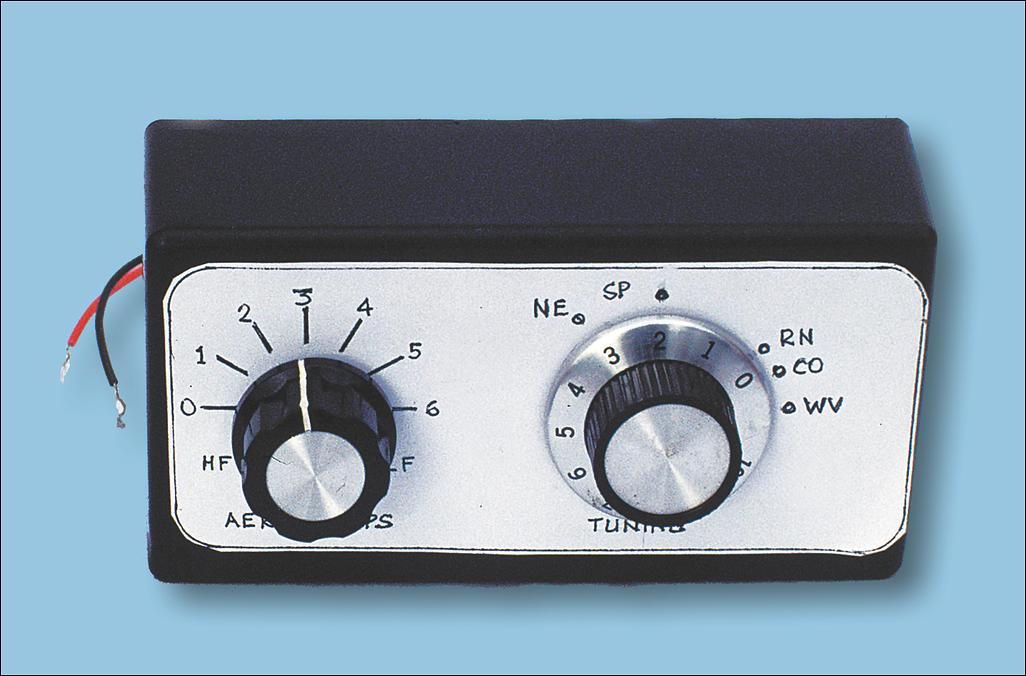
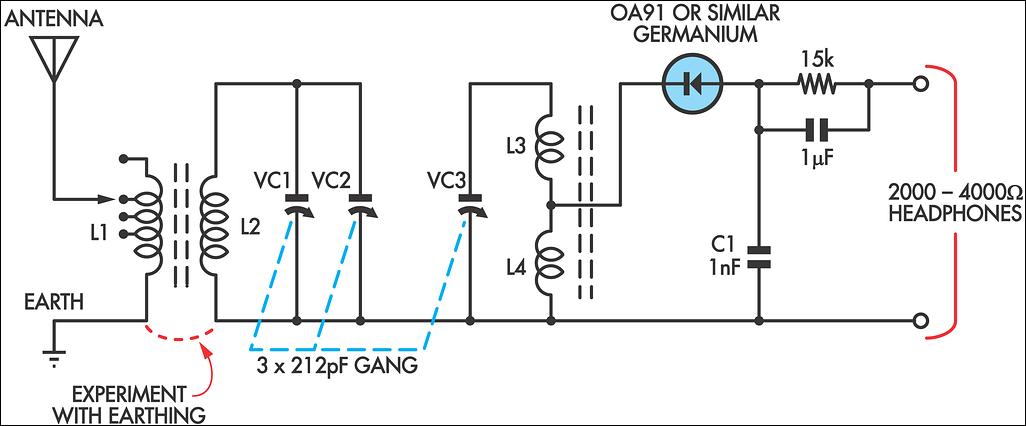
after the mid-1930s and the increasing power of AM broadcast
transmitters, large antennas quickly become redundant as far
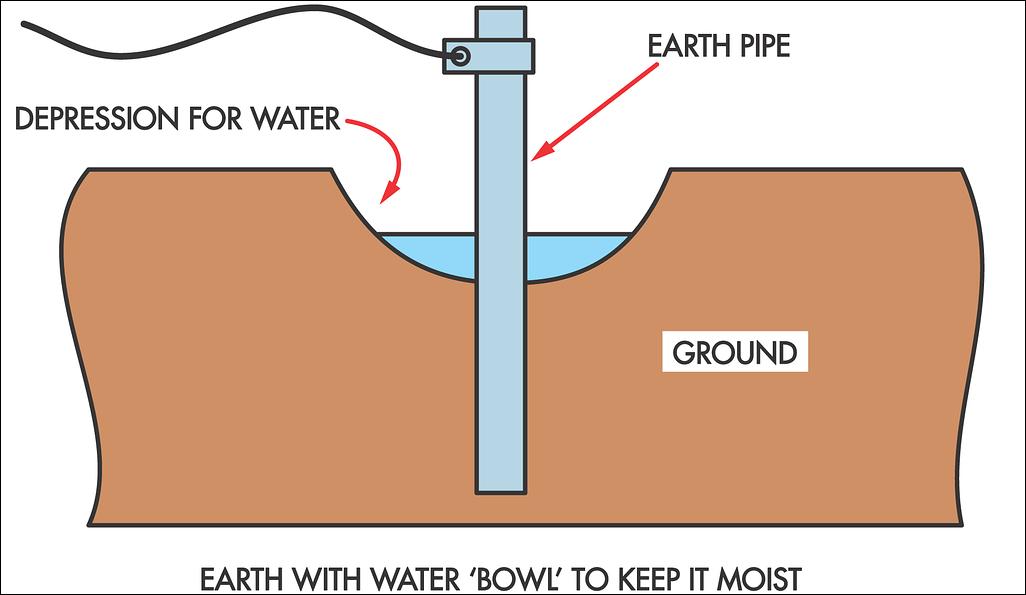
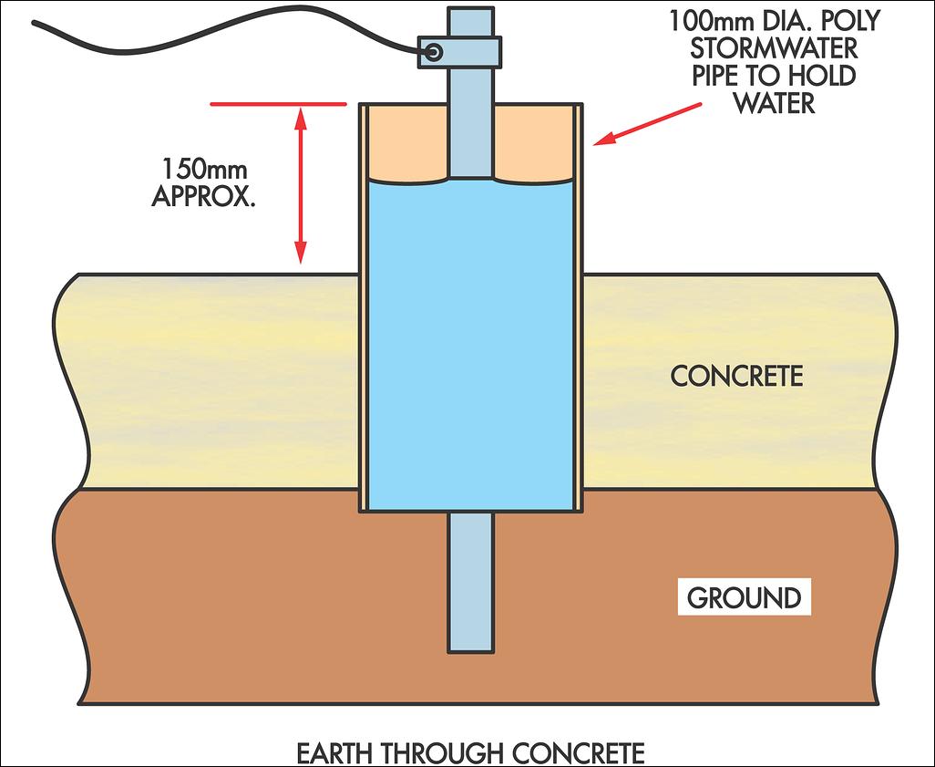
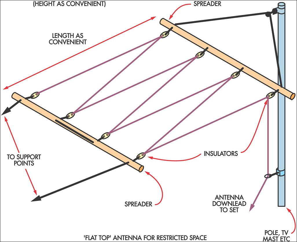
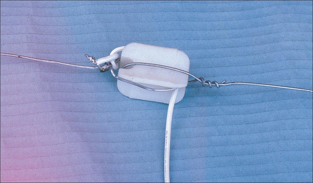
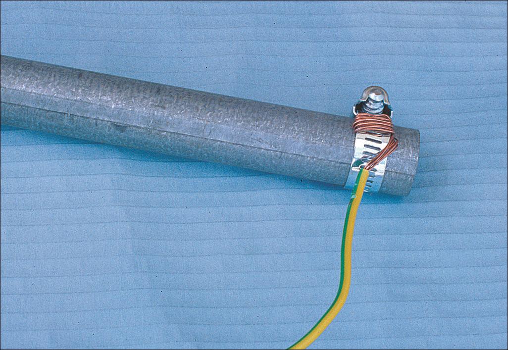
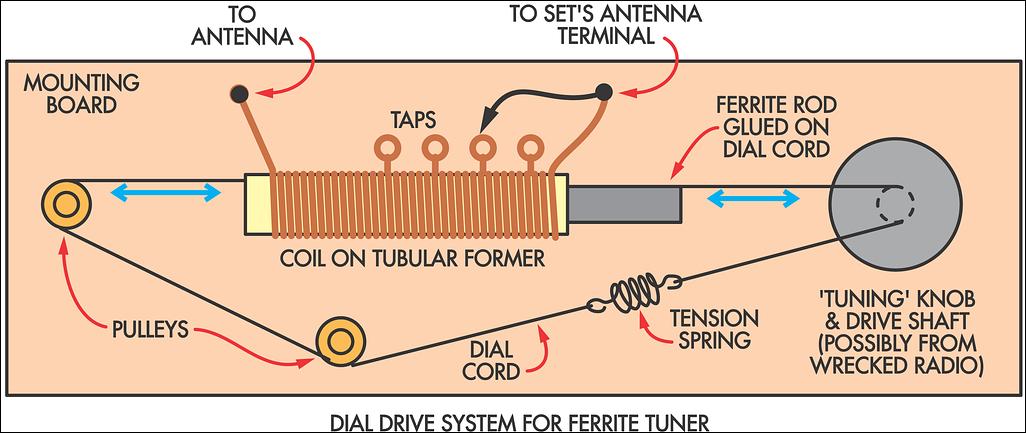
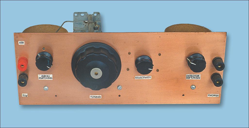
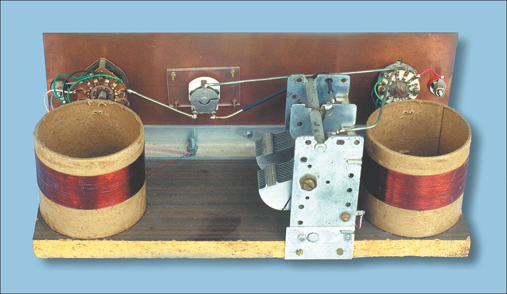
as the general public was concerned In fact, most people now don't like having to extend the whip antenna on a portable FM receiver to get the best reception Unfortunately, the use of metallic/bituminous insulation paper in the walls of many modern homes now acts as an RF shield, reducing the level of the radio signal penetration For this reason, good reception on older, less-sensitive receivers may require an outside antenna and this is particularly so for crystal sets In the November 1998, December 1998 and January 1999 issues, we looked at various methods for improving AM radio reception and reducing interference This article is not intended to supersede those articles but to give enthusiasts a few ideas on suitable antenna systems that will achieve good results in most situations The early days Experimental broadcasting commenced not long after the end of World War I Amateurs produced programs on a nightly or weekly basis and the general populace was keen to listen to these new transmissions The output power of these early experimental stations varied considerably but most were well under 100 watts The radiating systems connected to the transmitters were also quite varied, some consisting simply of an inverted "L" receiving type antenna fed against an earth that consisted of a metre or so of pipe driven into damp soil Others were more ostentatious, being something like the smaller broadcasting masts that can be seen around the countryside today Official broadcasting commenced in Australia in late 1923 (2SB/2BL) and the power of the stations varied from around 50W to 5kW (5000 watts) In most cases, the power ratings were for input power, not output power, so a 5kW transmitter may have had an output power of just 1.5kW Gradually the standards for broadcast transmitting stations became more uniform The commercial class B stations that came into being were rated at an output of 2kW in the country and 5kW watts in the city, whilst Class A (ABC) stations used upwards of 10kW (today, the ABC stations run upwards of 50kW in many instances.) At the same time, strategically placed low-power stations (50-500W) were used to provide signals in areas where the high power stations were relatively ineffective (such stations are still used today) Because of the low power of early transmitting stations and the general insensitivity of receivers up until the mid-1930s, large outside antennas were mandatory for reasonable reception during that period Many different antenna types were used in an attempt to get the best performance possible Some were a lot of work to install but may not have worked any better than much simpler structures But they did look commanding! A receiver using a large earth (mat) system (much like transmitting installations use) will work a little better than a receiver using the common, relatively inefficient receiver earths In practice, transmitting stations go for the most efficient antenna and earth system that is economically feasible That's because they need to provide the strongest signal possible for receivers that are using inefficient antenna systems, eg, a few metres of wire The reasoning here is that it is better to have efficient transmitting installations so that receivers can get by with convenient low-cost antenna systems Having said that, it is still necessary to use a relatively efficient antenna and earth system for low sensitivity receivers such as crystal sets Getting a good earth In an ideal situation, a 1-metre length of pipe or metal stake driven into the ground in a damp location will provide an adequate earth for most receivers This earth should be as close as practical to the receiver so that the minimum length of connecting wire is used back to the earth terminal of the receiver This also helps to reduce the effect of mains-borne interference, particularly in more sensitive receivers In my case, I have often used 19mm galvanised water pipes as the earth stake However, because I am an amateur radio operator, I need a better earth than a 1-metre length of pipe can provide For this reason, I commonly use up to three 2-metre lengths of pipe driven into the ground, leaving about 300mm above ground level The tops of the pipes/stakes are quite close and are bonded together but their bottom ends are quite some distance apart, as the pipes are driven into the ground at angles to each other In order for the earth to be effective, the whole length of the pipe/stake and the earth around it needs to be kept moist (not just the top few centimetres of the soil) This is achieved by making a small depression around the top of the pipe(s) and a bucket of water then poured into this depression at regular intervals A single pipe driven at least a metre into the ground is usually quite adequate as an earth for radio receivers (providing it is in moist ground) Fig.1 shows the details The wire (preferably multi-strand) going from the earth to the receiver earth terminal should be 1-2.5mm2 in cross-sectional area (equivalent to the average earth wire on the mains) It doesn't have to be insulated but insulated wire is easier to handle if it is likely to be close to any other metal, including the Sisalation type material used in the walls of modern homes Don't let a bare wire brush up against any metallic object as noise and "crackles" (interference) may be induced into the wire and thus into the receiver Unfortunately, it's not practical to solder the end of the wire directly to the earth stake or pipe That's because the metal mass is too great to allow it to get to the melting point of solder when using a soldering iron that's suitable for electronic work Instead, an electrician's earth clamp or a screw type hose clamp can be used to hold the earth wire firmly against the pipe The wire should be wrapped through the clamp a few times to make sure it will not move once clamped Before doing this though, clean the pipe using sandpaper to get rid of any oxidation at the contact point Once the earth wire has been clamped to the pipe, the assembly should be painted to stop any corrosion Alternative methods Not everyone has an ideal location to install earth stakes and so other methods of obtaining an earth must be used For example, many premises today have large areas of concrete which this can make things quite difficult One possibility but make sure that you check the locations of water, drainage, gas, telephone and electrical lines before doing this You will need a large masonry bit and a hammer drill for the job Begin by drilling a series of holes around the circumference of a circle large enough to accept a 100mm-diameter plastic stormpipe A cold chisel and heavy hammer will be required to break up the pieces but even so, it usually isn't easy getting the pieces out In fact, it's probably a good idea to send the family out for the day so that they don't learn any new words! The storm piping should protrude about 200mm above the ground and can be fixed into position using cement or silicone sealant This stormpipe is then filled with water to keep the earth pipe moist See Fig.2 If metal water pipes are used, it's possible to clamp the earth wire onto these and obtain quite good earthing However, earthing to a water pipe does raise the possibility of circulating currents through the pipe system and anything connected to the mains earth To overcome any chance of electrolysis (which can cause corrosion of the pipes), it's a good idea to install a capacitor in series with the earth wire near the radio This can range in value from .001?F up to 0.1?F - preferably one of each in parallel Note that this is necessary only if the receiver is mains operated and has its chassis earthed through the mains Gas pipes are not to be used under any circumstances For people in units, an earth via the mains may be the only viable alternative Any piece of electrical equipment that has a 3-core power lead and has its metal frame earthed can be used as the "earth" All you have to do is attach a wire from the metal frame of the earthed appliance to the earth terminal of the set This provides a reasonable earth but make sure the appliance has a relatively short lead to the power point Do not attempt to obtain a mains earth in any other way - the possibility of making a fatal mistake is much too great A good antenna The old saying of "the higher and longer the better" when referring to antennas for crystal sets and other low-performance sets is still true today If you live out on a farm, erecting an effective antenna is relatively easy A good standby is the old standard inverted "L" antenna some 30 metres long across the top and 13 metres high "Higher and longer" will capture even more signal and possibly also lightning, so lightning arresters are desirable on antennas of this size Most of us do not have the wide open spaces to install this type of broadcast receiving antenna so we have do the best we can with the available space It's also necessary to comply with local council bylaws In most cases, any antenna that's erected will be a compromise between performance and available space The installation must also be safe and must not be an eyesore to neighbours or others living on the premises It is possible to run an antenna (flat top section) around the yard, with one end attached to the chimney (if the house has one) or to a TV antenna mast See Fig.3 Specialist TV antenna supply shops, such as Lacey's Australia in Frankston, Victoria, have a wide variety of TV antenna mounting masts, brackets and other items which can be used for this job A number of the advertisers in SILICON CHIP, such as Jaycar, Dick Smith Electronics and Altronics, also have a range of TV-antenna bits and pieces Check out their catalogs and you should have little difficulty in choosing the necessary parts to make your antenna effective, safe and aesthetically pleasing Commonly, in the past where there was little space for an antenna, it was made to look something like a clothes line As shown in Fig.3 This is an effective way of getting a considerable length of wire up into the air in a confined space It may not be as effective as a long, straight run of wire but it is still quite good Regrettably, some people are not allowed to have any outside antenna system at all (perhaps for "aesthetic" reasons) However, all is not lost as outside antenna systems can be erected at night by suitable mechanisms and pulled down after use Some people have even disguised an antenna mast as a flag pole A little ingenuity is sometimes needed here If that doesn't suit, an antenna in the ceiling space can be much better than nothing at all There are a few provisos, however - the house must have a gable roof and the roofing must not be metallic Nor should there be any metallic foil underneath the tiles (metal acts as a shield for radio signals) To build a ceiling space antenna, install several folded lengths of insulated wire near the peak of the roof and bring one end down to where the receiver is located Thirty metres of wire should give reasonable performance It certainly won't be up to the standard of a high outside antenna but it's much better than nothing Antenna wire An outside antenna lead can be made from single or multi-strand copper or galvanised iron wire It can be insulated or bare but it must not too thin, otherwise it will break in the wind or if a bird flies into it I use common gardening tie wire (available at hardware stores) of around 16 gauge - it's cheap and solders quite well If you use bare wire, it is necessary to also use egg insulators (available from stores selling electric fence components and major electronic stores) at the points where it is supported Alternatively, the polyproylene pipe used for gardening systems can be used in some situations The down lead to the receiver from the antenna should be run using insulated multi-strand cable, such as one half of twin-flex cable used on small electrical appliances Any joins in the antenna wire must be soldered If they are not soldered, scratchy noises will be heard in the radio or variations in level will occur after only a few weeks That's because the wires oxidise and intermittent good and bad contact between the joined wires will occur Finally, to alleviate any stress on the lead in, it should be attached to the antenna proper in a manner similar to that shown in one of the photos Optimising performance A normal AM broadcast antenna is an aperiodic device, meaning that it is not tuned to any particular frequency By contrast, if it were tuned to a specific frequency, the amount of signal picked up by the antenna would rise noticeably In other words, tuning the antenna system can greatly improve its performance and this can be done quite easily Fig.4 shows the details First, obtain 150mm of 20mm-diameter PVC electrical conduit and wind about 180 turns of 0.5mm (24B&S) enamelled copper wire onto it, with tappings made at every 20 turns The tappings can be made by inserting a match under a turn, winding some more turns on and then sliding the match further along as you progress, keeping each tapping point proud of the coil One end of the finished coil is then wired in series with the antenna lead, while a "fly lead" fitted with a small alligator clip is soldered to the other end This fly lead allows sections of the coil to be shorted out if necessary Alternatively, either the antenna or the receiver aerial lead can be terminated on one of the terminals along the coils, as shown in one of the photographs Once the coil is in place, it is then time to trial the tuner by sliding a 180mm-long (not critical) x 9mm-diameter ferrite rod into the coil and observing the results Try different coil tappings until you get the best performance Once the correct tapping is found for the coil, altering the position of the ferrite rod in the coil will peak the performance on any particular station Note that this coil will also work with the average domestic receiver, although its performance at the low-frequency end of the dial can be unpredictable due to the way some aerial coils were designed More turns may be required on the peaking coil in some cases Initially, the rough and ready method described above will give good results However, it can all be made much tidier Excess turns on the coil can be removed if desired and a more sophisticated method of adjusting the position of the ferrite rod inside the coil can be constructed See Fig.4 Jaycar Electronics can supply suitable ferrite rods (Cat. LF-1012) for an antenna tuner but loopstick antenna rods scrounged from defunct sets are also quite suitable - just remove the windings from the rod If the rod has been broken and you have all the pieces, it is often possible to effectively rejoin them provided the breaks are clean and the two sides of a break mate without gaps You can use Araldite or some other similar adhesive for this job Crystals sets and antenna tuners On my own crystal sets, I can receive just one station without the antenna tuner By contrast, if the antenna tuner is used, I can receive four stations, including a Melbourne station some 150km away! The tuning is also much sharper than normal and the aerial tapping is quite low on the coil Initially, however, I found that the crystal sets were not performing at all well, barely receiving the local station just 20km away I tested the germanium diodes using the diode tester function on my digital multimeter and found that the forward voltage drop had increased from 0.2V to 0.8V, while the reverse voltage conduction point was down to 3V The diodes were consigned to the rubbish bin and new ones installed The crystal sets in the photos belong to members of the local vintage radio club Two are very nice looking sets and perform quite well The small one in the jiffy box (130 x 65 x 40mm) is extremely interesting as it uses ferrite cores on all coils and a tapped antenna loading coil (possibly to resonate the antenna) I have not heard this latter set in operation but have heard others claim that it is a particularly good performer As a result, its circuit is enclosed for readers who may care to experiment See Fig.5 All the coils are wound using 0.5mm (approx.) enamelled copper wire L1 and L2 are wound on the same piece of ferrite rod but at opposite ends of the rod which is around 50mm long Coils L3 and L4 are wound on two ferrite rods, each around 30mm long The amount of coupling between L2 and L3/L4 is open to experimentation - around 50mm apart should give good results Summary A high and long antenna coupled with a good earth system is important if worthwhile results are to be obtained from crystal sets and other low-performance sets In some cases, it may also be necessary to tune the antenna to the frequency of the desired radio station (ie, by using an antenna tuner) As for crystal sets, the best performing types are those using two tuned circuits As in Fig.5 Also, it's necessary to use a germanium diode for the detector and a pair of high-impedance (2-4k?) headphones |